Process Safety · Lesson 54 · 10 min read
A Heat-Exchanger Tube Rupture Can Overpressure the Low-Pressure Side
A shell-and-tube heat exchanger deliberately places two process systems close together. If the tube side operates at much higher pressure than the shell side, a failed tube can create an internal loss of containment: high-pressure fluid enters equipment and piping that may never have been designed for that pressure. The escalation can be rapid, extend beyond the exchanger and introduce flammable, toxic or reactive material into an unexpected system.
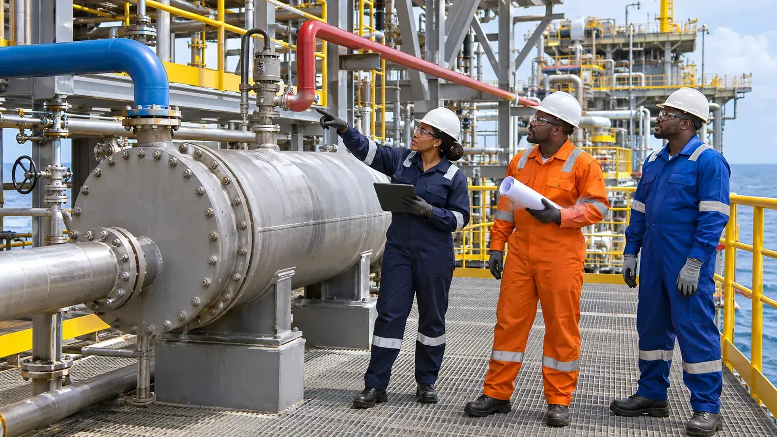
The hazard mechanism: high pressure finds the weak side
Exchanger tubes can lose integrity through corrosion, erosion, vibration, fatigue, thermal cycling, fouling-related overheating or other service-specific damage. Once a tube opens, the pressure difference drives fluid from the high-pressure side into the low-pressure side. Gas can compress low-pressure inventory, liquid can displace it, and a flashing fluid can generate a larger vapour volume. The pressure rise may affect the shell, connected pipework, downstream vessels and a utility return header.
The important boundary is therefore not only the exchanger shell. It is the full low-pressure system that can be exposed. A relief device fitted nearby is useful only when its inlet and discharge paths remain available, its capacity and response match the assessed scenario, and the discharge reaches a safe destination.
What official guidance requires teams to consider
UK HSE's heat-exchanger technical guidance lists tube rupture among the major design problems that may affect safety. It expects the safety case to show that credible failure modes and consequences have been considered and that prevention, control and mitigation measures are selected. For overpressurisation, HSE identifies design codes, operating and maintenance procedures, alarms, trips, relief systems and vent systems as relevant measures.
HSE's relief-system guidance starts with the hierarchy: eliminate or reduce the pressure hazard where practicable, contain the maximum feasible pressure where justified, and then apply suitable protective systems. It also says relief devices must not be isolated from protected equipment while in use, discharges should reach a safe location, and the design basis and methodology should be documented and controlled through management of change.
Operational analysis: protection is a system, not a valve
A tube-rupture review begins with actual operating and design conditions on both sides. The team considers credible compositions, phases and pressure differences during normal operation, startup, shutdown, blocked flow and utility changes. It then traces where the high-pressure fluid could travel and asks whether every exposed component can contain or safely relieve the transient.
Inspection and monitoring reduce rupture likelihood but do not replace consequence protection. Examination plans must target the active damage mechanisms and locations most likely to thin, crack or vibrate. Process indications can provide early warning: an unexpected low-side pressure rise, contamination, composition change, utility-return upset or temperature shift may indicate tube leakage. Alarm response must tell operators what to isolate, what not to isolate, and how to avoid trapping pressure or disabling relief.
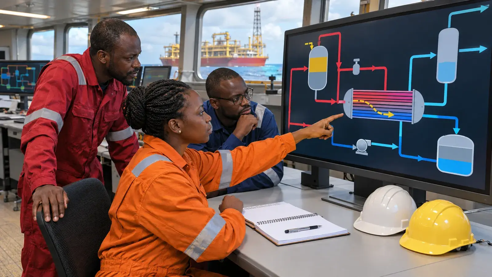
Hypothetical FPSO example: gas cooler tube failure
Hypothetical example—not a documented incident: On an FPSO, high-pressure produced gas flows through the tube side of a shell-and-tube cooler. A lower-pressure cooling medium circulates on the shell side and returns to a common utility header. The control room receives a rapid shell-side pressure rise and a hydrocarbon indication in the utility return.
Operators follow the approved response: reduce and isolate the high-pressure source using designated controls, protect personnel from the affected area, maintain the engineered low-side relief route, and monitor the connected utility system for escalation. They do not close valves merely to stop the alarm if that action could trap inflow or isolate protective devices. After stabilisation, specialists determine the failure mechanism, inspect similar exchangers and verify the tube-rupture design basis before return to service. The example does not prescribe a universal trip setting, relief size or isolation sequence.
Critical controls
Credible design basis: document actual high- and low-side pressures, fluid behaviour, credible tube-failure cases and the connected low-pressure system. Revalidate after changes in feed, throughput, utility routing or equipment.
Overpressure protection: confirm that containment, open flow paths, relief devices and safe discharge arrangements protect every exposed component for the assessed case. Keep required isolation valves in their controlled safe position.
Damage-mechanism inspection: use competent engineering to select examination methods, coverage and intervals for the exchanger's materials, service, age and degradation history. Treat unexpected wall loss, vibration or leakage as operating decisions.
Detection and response: define useful pressure, composition, hydrocarbon or utility-quality indications; make alarms actionable; and rehearse the response without disabling the relief path.
Leadership actions
Leaders should require a current tube-rupture scenario in process hazard analysis and relief documentation wherever a significant pressure difference exists. The review must include upstream and downstream low-pressure equipment, not stop at the exchanger nozzle. Technical authorities should own assumptions, calculation methods, inspection inputs and the effect of modifications.
Operations, integrity and process engineering should review emerging evidence together. A small cross-contamination trend may be an early barrier warning. Production pressure must not normalise repeated utility contamination, unexplained pressure spikes or overdue exchanger examination.
Three practical actions
- Trace the exposure: select one high-pressure exchanger and follow the low-pressure side through every connected vessel, pipe and common header.
- Verify the protection: confirm the documented tube-rupture basis, relief availability, safe discharge destination and controlled valve positions.
- Test the response: ask what indications would reveal a leak or rupture and whether operators know how to isolate the source without trapping pressure.
Takeaway and team discussion
Key takeaway: a tube rupture turns the high-pressure side into a pressure source for the entire connected low-pressure system; protection must cover that complete path.
Discussion question: which heat exchanger has our largest pressure difference, and can current evidence show that every exposed low-pressure component is protected?
Continue in the Process Safety hub, and connect this lesson with relief availability, safe relief discharge and mechanical integrity.
Verified primary references
- UK HSE: Heat exchangers—failure modes and technical measures.
- UK HSE: Design codes—plant, including heat-exchanger tube rupture.
- UK HSE: Relief systems and vent systems technical measures.
- UK HSE: Introduction to pressure equipment and protective devices.
Video check: no directly relevant official incident or technical video specifically addressing high-pressure-to-low-pressure heat-exchanger tube rupture was identified, so no unrelated video is embedded.
Published and sources checked 5 November 2026. Educational discussion only: apply the installation's approved safety case, relief design basis, process hazard analysis, procedures and integrity-management programme.
Your experience matters
Share your thoughts on this page
Have a question, a useful experience or a suggestion? Add your input below.
Comments are public. Keep them respectful and relevant. Do not share contact details, confidential information or emergency reports.
Comments on this page
Loading comments…