Process Safety · Lesson 31 · 8 min read
Trapped Liquid Can Build Pressure Without a Running Pump
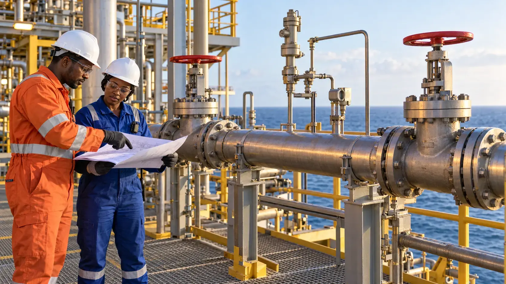
A pump does not need to be running for pressure to rise. When liquid is trapped between closed valves, even ordinary warming can expand the liquid inside a space that offers very little room to absorb that change. If the blocked-in section has no effective relief path, pressure can increase until a gasket leaks, a fitting fails or pressure-containing equipment ruptures.
Why blocked-in liquid deserves attention
Liquids are often treated as incompressible for practical engineering calculations. That useful approximation also explains the danger: a completely liquid-filled section has little capacity to accommodate expansion. Heat may come from sunlight, ambient temperature, steam tracing, a hot adjacent process, recirculation, fire exposure or an operating change that reconnects a warm source. The temperature change may look modest while the resulting pressure challenge is severe.
The vulnerable space can be a short spool between two manual valves, the shell side of an isolated heat exchanger, a pump casing, a loading hose, a sampling system, a chemical-injection line or a long transfer pipeline. The pressure source is not necessarily a pump or compressor. It is the combination of trapped liquid, increasing temperature and an unavailable or inadequate path for expansion.
This makes the hazard easy to miss during shutdown, maintenance and standby conditions. A line may be described as isolated or out of service, yet it still contains liquid and remains exposed to heat. An isolation drawing can show the intended valve positions without making the hydraulic volume or thermal-relief dependency obvious. The correct question is therefore not only, “What is feeding this section?” but also, “What happens to every liquid-filled volume after these valves close?”
What an official investigation demonstrated
The U.S. Chemical Safety Board investigated the 13 June 2013 explosion and fire at the Williams Olefins plant in Geismar, Louisiana. During non-routine operational activity, heat was introduced to an offline reboiler that contained a liquid propane mixture. The reboiler was isolated from its pressure-relief device. The CSB concluded that liquid thermal expansion produced a rapid pressure rise and catastrophic rupture. Two workers were killed and 167 injuries were reported.
The lesson is broader than one heat exchanger. Equipment status can change the availability of protection. A relief valve may exist in the design, yet closed isolation valves, temporary line-ups or modifications can remove it from the trapped inventory. Process hazard analyses, management-of-change reviews and pre-startup checks must consider credible operating, standby, shutdown and maintenance configurations—not only the normal operating diagram.
A practical offshore scenario
Hypothetical example: An offshore hydrocarbon transfer line is isolated at both ends after flushing. A low point remains liquid-full. The section runs across an exposed deck and warms in direct sunlight after a cool night. The pump is stopped, both boundary valves are closed and the control room sees no active flow. Those observations do not prove the trapped section is pressure-safe. Unless the line has a suitable, available thermal-relief path or another engineered means of accommodating expansion, the pressure boundary may be challenged without a clear operating alarm.
Critical controls
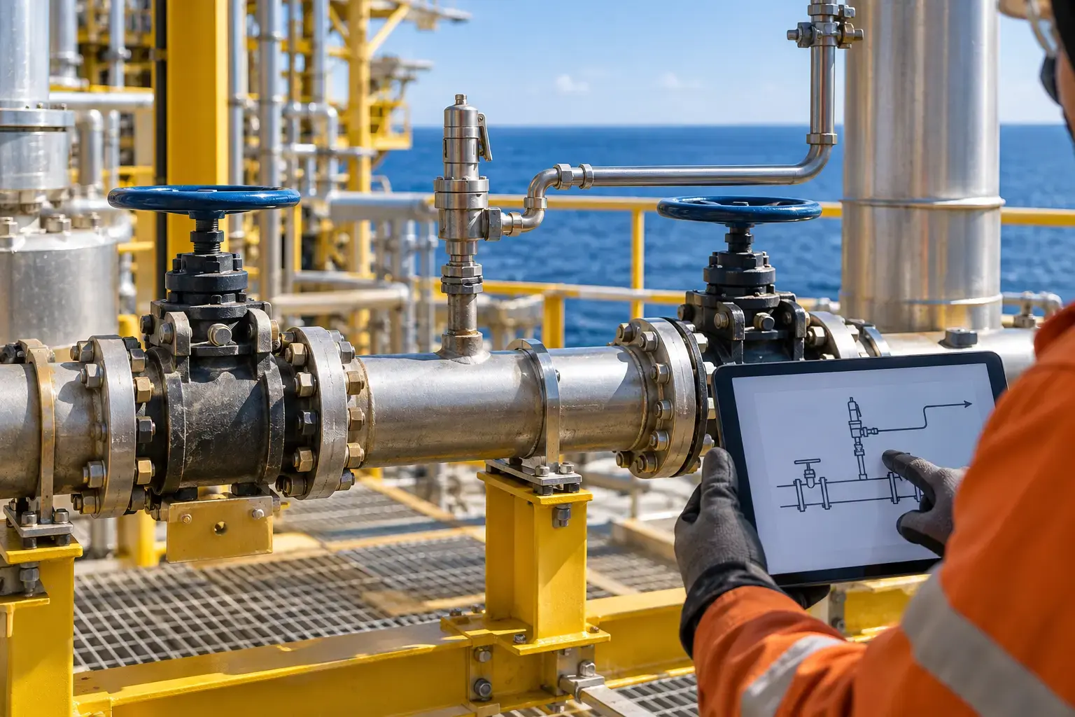
Identify every credible blocked-in volume. Review piping and instrumentation diagrams, isolation philosophies and field arrangements for sections that can become completely liquid-full. Include normal operation, shutdown, maintenance, temporary hoses, standby equipment and unusual valve combinations. Field verification matters because undocumented changes, locked valves and local bypasses can alter the real pressure path.
Provide an engineered protection method. Depending on the service and design basis, protection may include a thermal-relief valve, an expansion chamber, a permanently available route back to suitable process equipment or another competent-engineering solution. The discharge destination must also be safe and compatible. A small relief device is not automatically adequate merely because the expected flow is small; set pressure, capacity, backpressure, fluid properties and destination remain design matters.
Keep the relief path available. Where isolation valves are permitted around a relief device, their required position and administrative control must be unmistakable and verifiable. Car-seals, locks, line-up checks and independent verification are useful only when they match the approved design and are sustained in the field. Any valve closure that separates liquid inventory from protection changes the risk.
Control heating sources and reinstatement. Steam tracing, electrical heat tracing, warm process connections and solar exposure should be considered before isolating liquid. After maintenance, verify that blinds, valves and relief paths are restored to the approved configuration before introducing inventory or heat. If the configuration is uncertain, stabilise the equipment and obtain competent technical support.
Leadership actions that prevent recurrence
Leaders should require isolation reviews to address pressure development after isolation—not just prevention of incoming flow. This is particularly important when equipment moves between operating, standby, out-of-service and maintenance status. Temporary operating instructions and management-of-change reviews should identify who owns the trapped inventory, how long the condition may remain, which limits apply and what restores the normal design.
Inspection and testing programmes should confirm that thermal-relief devices remain suitable, correctly set, connected to the intended destination and free from isolation or blockage. Repeated small leaks, lifted relief valves, distorted gaskets or unexplained pressure when equipment is idle should be treated as process-safety information. Correcting the symptom without understanding the pressure source can leave the initiating mechanism in place.
Actions for today
- Choose one liquid service and trace every volume that can be trapped between closed valves during normal and non-routine line-ups.
- Verify the actual field route from that volume to its intended thermal-relief device and safe destination.
- Check whether heat tracing, sunlight, hot equipment or a changed line-up could warm the trapped inventory, and escalate any uncertain protection through the approved process.
Official incident video
Blocked In
Official U.S. Chemical Safety Board investigation video about the Williams Olefins explosion and the consequences of heating liquid isolated from pressure relief.
Team discussion question
Which liquid-filled section on our installation can be isolated from its normal relief path, and what evidence proves it remains protected as temperature changes?
Your experience matters
Share your thoughts on this page
Have a question, a useful experience or a suggestion? Add your input below.
Comments are public. Keep them respectful and relevant. Do not share contact details, confidential information or emergency reports.
Comments on this page
Loading comments…